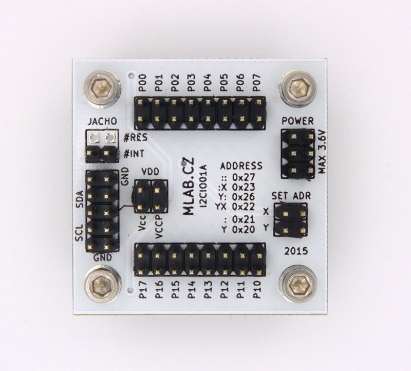

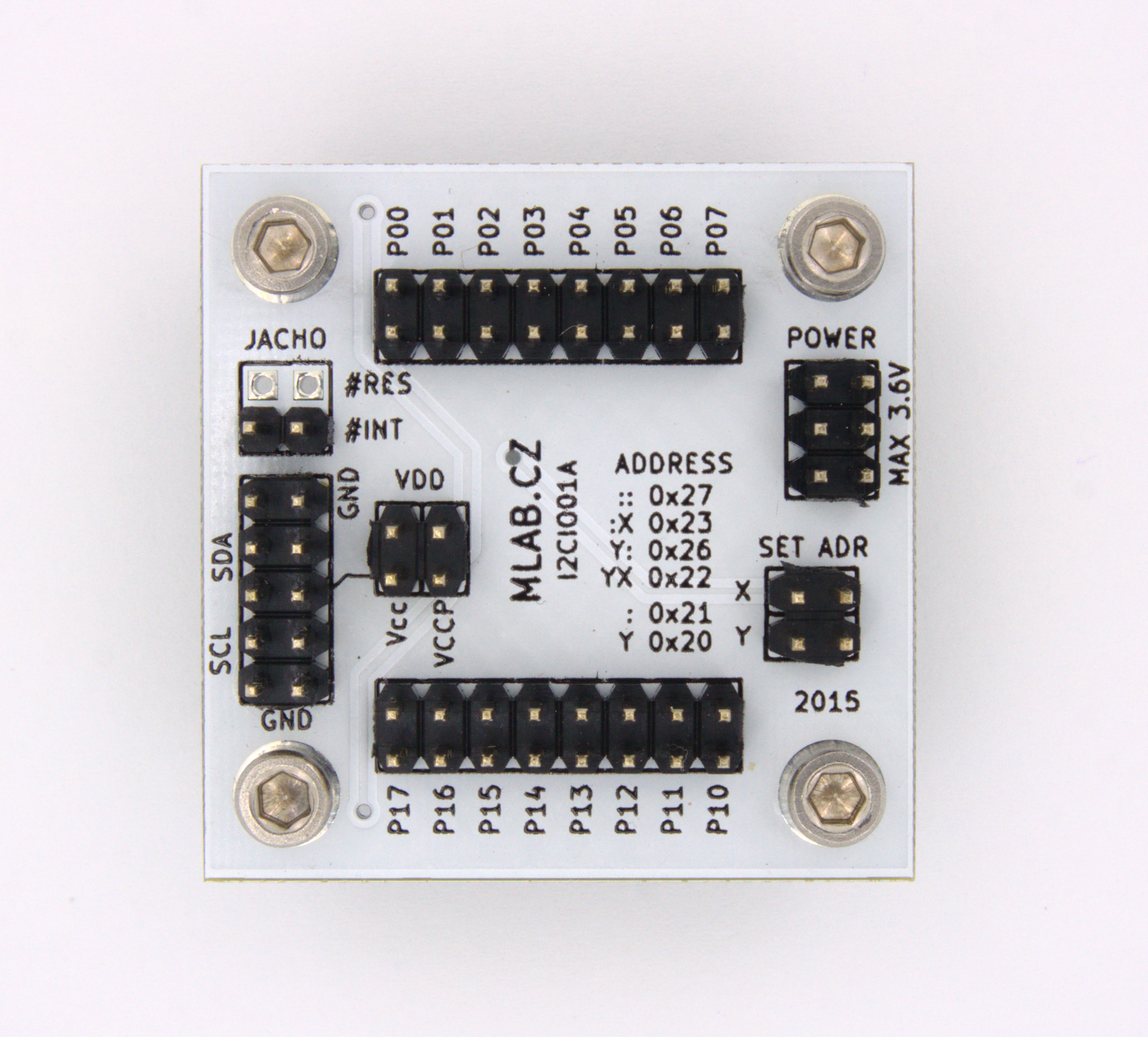


The I2CIO01 module is a GPIO expander designed for operation in the range of 1.65 to 5.5 V. It provides general-purpose remote I/O expansion via the I²C interface. The module comprises two 8-bit Configurable, Input Ports, Output Port, and Polarity Inversion registers.
| Parameter | Value | Note |
|---|---|---|
| Power Supply | Max. 3.6 V | |
| ICs Used | TCA6416A or TCA9535 | |
| Interface bus | I²C | Frequency up to 400 kHz |
| Main Usage | I²C IO expander | |
| Dimensions | 40.13 x 40.13 x 16 mm | Height above the baseboard |
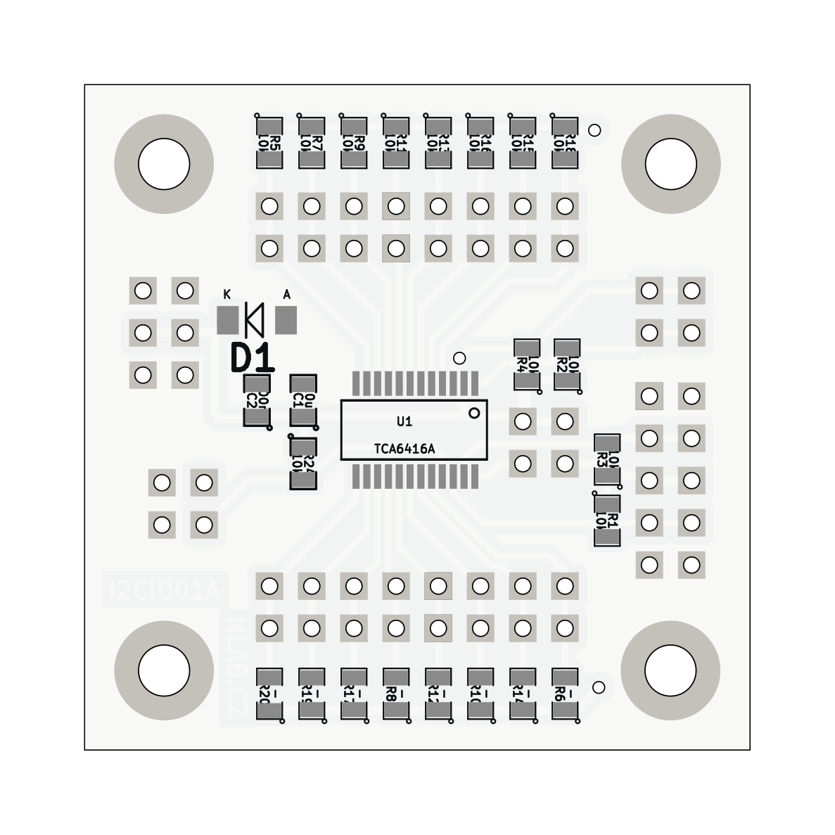
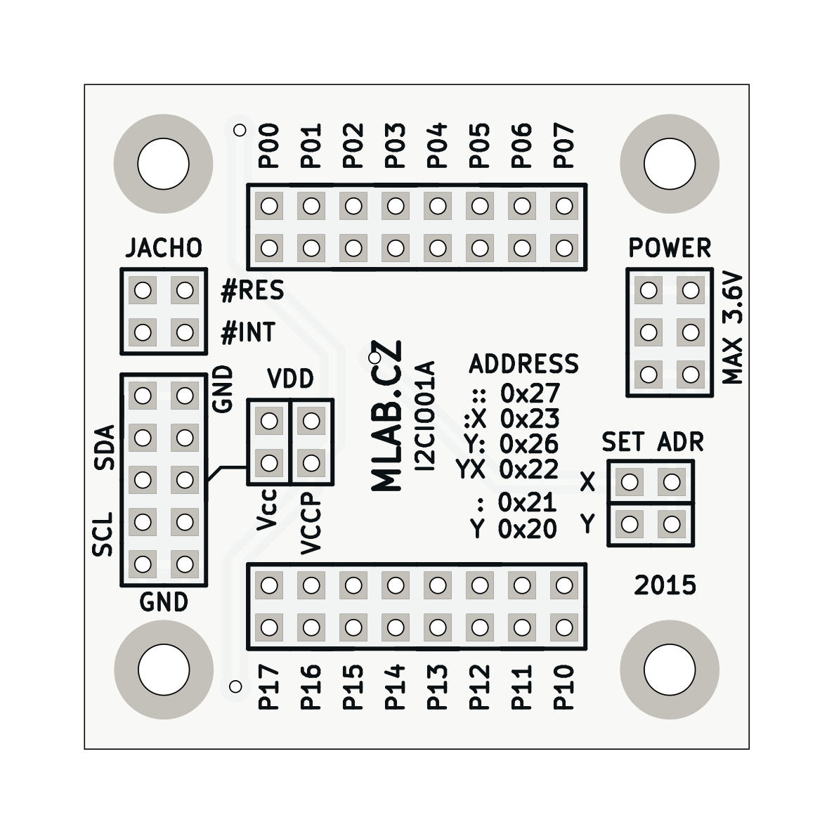
The module's design and layout files can be found in the hw/sch_pcb directory. The board is designed using KiCad.
| Designator | Type | Package | Quantity |
|---|---|---|---|
| J3 | JUMP_3X2 | Pin_Header_Straight_2x03 | 1 |
| R1, R2, R3, ... | 10k | SMD-0805 | 13 |
| U1 | TCA6416A | TSSOP-28 | 1 |
| J8, J5 | CONN1_2 | Pin_Header_Straight_1x02 | 2 |
| P1, P2, P3, P4 | MountingHole_3mm | 4 | |
| J1 | JUMP_2X2 | Pin_Header_Straight_2x02 | 1 |
| J2 | JUMP_5X2 | Pin_Header_Straight_2x05 | 1 |
| J6, J7 | JUMP_8X2 | Pin_Header_Straight_2x08 | 2 |
| J4, J9 | CONN_2 | Pin_Header_Straight_1x02 | 2 |
| C1 | 10uF | SMD-0805 | 1 |
| C2 | 100nF | SMD-0805 | 1 |
| D1 | BZV55C-3,6V | Diode-MiniMELF_Standard | 1 |
For more detailed information on each component, please refer to their respective datasheets:
Contributions are welcome! Please fork this repository and submit a pull request with your changes.
For more information, visit the MLAB website or contact us at support@mlab.cz.